
The Science Behind the Output
How a two-blade downwind rotor with NASA LS-1 blades converts moving air into 300 kW of usable power — the governing equations, an interactive estimator, and the blade-vortex physics at work in the wake.
The two‑blade downwind HAWT employing the NASA LS‑1 airfoil series, The rotor is structurally tailored as a passive aeroelastic load‑attenuation system: spanwise distributions of flap wise bending stiffness (EI), torsional rigidity (GJ), and laminate coupling terms (notably D16/B16 from the ABD matrix) are tuned to achieve a prescribed bend–twist coupling coefficient. Under elevated aerodynamic loading, this induces a controlled twist‑to‑feather response that reduces sectional angle of attack, suppresses nonlinear lift‑curve excursions, and mitigates extreme gust loads across IEC 61400‑1 DLC 1.3, 1.4, 2.3, and 6.x.
The downwind configuration shifts tower‑shadow interaction into a favorable phase relationship with the blade’s first and second flap wise eigenmodes, reducing modal amplification and improving fatigue‑life margins under DLC 1.2 and 1.4 turbulent inflow. Because the rotor operates leeward of the tower, the nacelle–rotor assembly functions as a free‑yaw system, naturally aligning with the inflow without requiring a yaw‑retention gearbox or high‑stiffness yaw‑drive assembly. This eliminates yaw‑system torque‑retention requirements, reduces yaw‑bearing moment spectra, and simplifies drivetrain torsional load paths.
The design has an aerodynamic limiter that shuts the turbine down at high excessively high windspeeds, the blade hub is supported by elastomeric bearings to absorb vibrations and reduce bending force transmission to the tower assembly.
The tower and guy cable stiffness contributes to the dynamic behavior of the total assembly offering damping and a shock absorption mechanism.
The turbine’s structural‑dynamic architecture is validated through full Campbell‑diagram analysis, tracking rotor‑speed‑dependent eigenfrequencies against excitation harmonics (1P, 2P, 3P, and tower‑shadow harmonics). The downwind rotor’s passive aeroelastic behavior shifts the first flap wise mode downward and introduces beneficial damping, preventing critical crossings with the 1P line across the operational rotor‑speed envelope. The second flap wise and first edgewise modes remain sufficiently separated from 3P excitation, maintaining positive damping ratios and avoiding modal coalescence.
The absence of a yaw‑retention gearbox reduces nacelle mass and shifts the global yaw–tower coupled mode to a lower frequency, but still well below the 1P excitation band. This ensures no low‑frequency resonance occurs during startup, shutdown, or free‑yaw transients. The resulting Campbell diagram exhibits clean separation between structural modes and excitation harmonics, with no unstable crossings or flutter‑susceptible regions across the entire operating range.
The turbine’s aeroelastic performance is validated using nonlinear, time‑domain simulations in Nastran/Ansys/Adams/ HAWC2‑class solvers, incorporating:
- generalized aerodynamic forces via unsteady BEM with dynamic inflow and dynamic stall models,
- geometrically exact beam formulations for blade structural dynamics,
- full 6‑DOF nacelle–yaw–tower coupling,
- nonlinear torsion–bending coupling from laminate‑level stiffness matrices,
- stochastic turbulent inflow fields (Kaimal/Mann spectra) for DLC 1.2/1.3,
- fault‑induced transient simulations for DLC 2.3 and 6.x,
- and aeroelastic stability analysis via p‑k or eigenvalue‑tracking methods.
Simulation results confirm that the downwind rotor’s passive bend–twist coupling provides significant load relief during gusts, reducing flapwise root bending moments and suppressing transient overshoots. The aeroelastic damping remains positive across all operational rotor speeds, with no evidence of flutter, torsional divergence, or mode‑coupling instabilities.
Power in the Wind
The kinetic power flowing through the rotor disc rises with the cube of wind speed — double the wind, eight times the available power.
Captured Power & Coefficient of Performance
Only a fraction Cp of the wind's power can be captured. Well-designed two-blade rotors reach Cp ≈ 0.45–0.48.
Tip-Speed Ratio
Two-blade rotors run best at a high tip-speed ratio (λ ≈ 6–8), where the LS-1 blade sees a clean, efficient angle of attack.
The Betz Limit
No wind turbine can extract more than 16/27 of the wind's kinetic energy — a hard physical ceiling derived by Albert Betz in 1919. Every Cp figure on this site is measured against it.
Annual Energy Production
Yearly output depends on the capacity factor (CF) — the share of rated power actually delivered across a year of varying wind. Distributed sites typically see CF ≈ 25–35%.
Lift-Driven Rotation
Each LS-1 blade section is an aerofoil: oncoming flow generates aerodynamic lift (L) that drives the rotor, while shed vorticity forms the wake shown below.
Visualizing the Wake
As the LS-1 blades generate lift, they shed organized vorticity into the air behind the rotor. These technical diagrams illustrate the structures that govern wake behavior and turbine spacing.
Sectional Lift & Tip Vortex
Flow over the LS-1 aerofoil section produces lift; pressure difference at the blade tip rolls up into a concentrated tip vortex.
Helical Trailing Wake
The tip vortices from each blade trail downwind in interlocking helices, defining the rotor's wake and recovery length.
Wake Expansion & Spacing
Extracting energy slows and widens the flow behind the rotor — the reason turbines in arrays must be spaced several diameters apart.
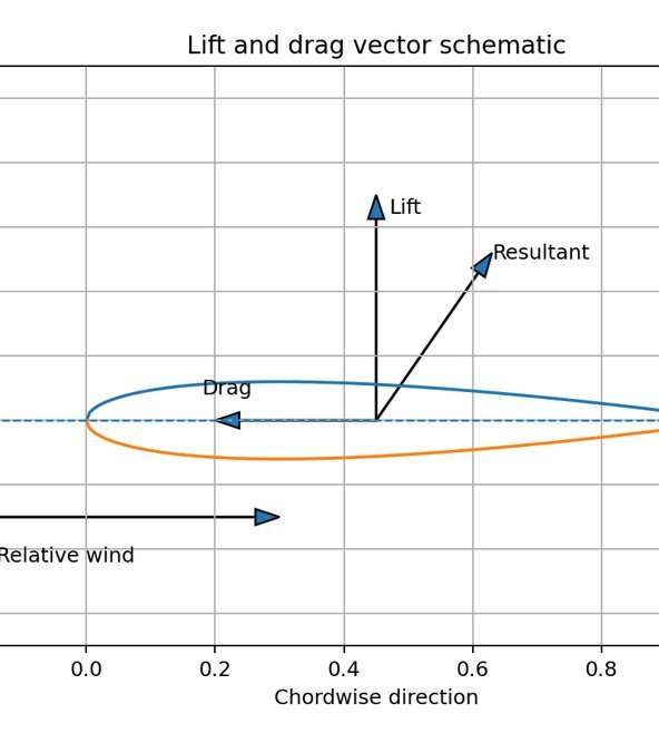
Lift & Drag Vectors
The aerofoil resolves the relative wind into a large lift force perpendicular to the flow and a small drag force along it; their resultant is what drives the rotor.
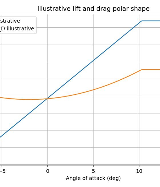
Lift & Drag vs Angle of Attack
Lift rises almost linearly with angle of attack until stall, while drag stays low through the working range — the gap between the two curves is the blade’s useful operating band.
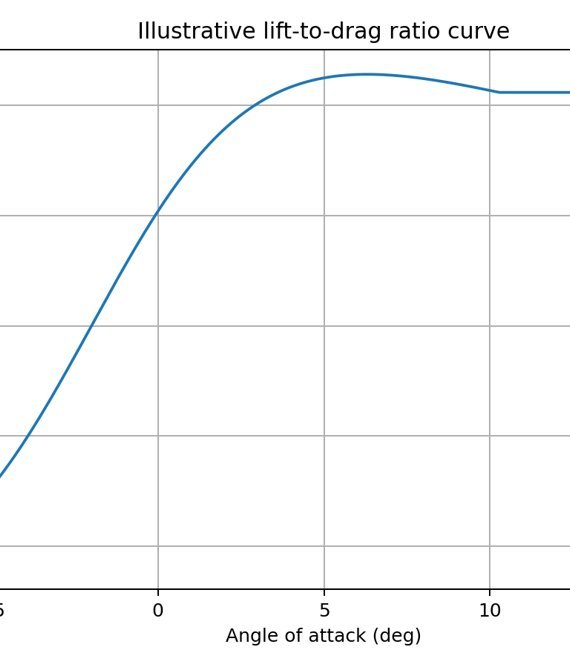
Lift-to-Drag Ratio
The lift‑to‑drag ratio peaks at a few degrees angle of attack; blades are designed to run near this peak, where each unit of drag buys the most lift.
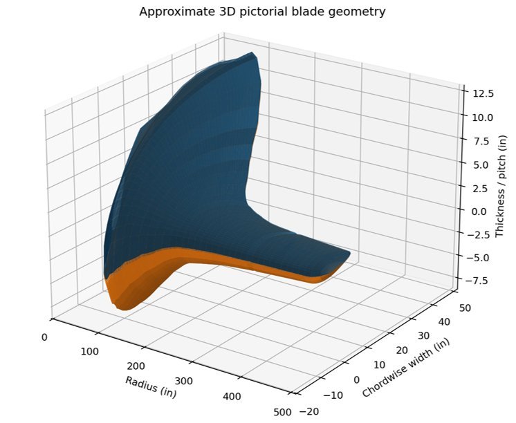
3D Blade Geometry
An approximate three‑dimensional view of the blade — twist and taper from root to tip, with the aerofoil sections thinning and pitching along the span to hold an efficient angle of attack at every radius.
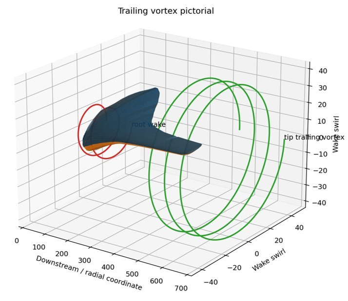
Trailing Vortex System
A pictorial of the wake: a strong tip‑trailing vortex spirals downstream from the blade tip while a weaker root wake forms inboard — the rotating structures that set turbine wake behaviour and spacing.
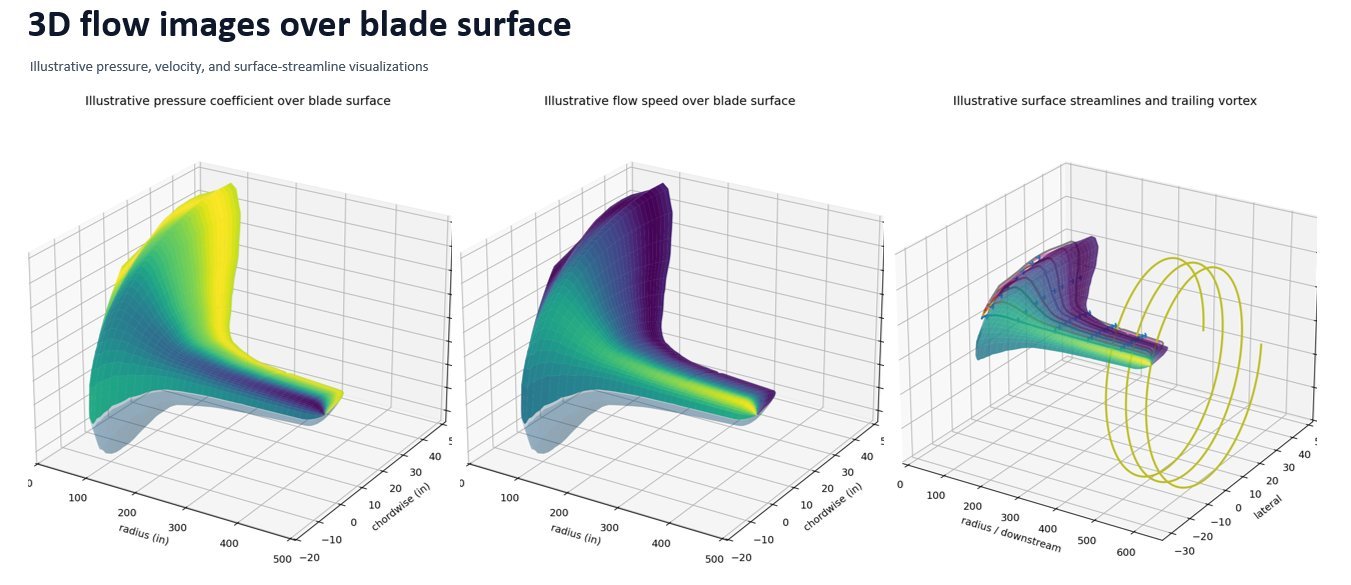
NASA Mod-1 Blade Mathematics
The two-blade downwind architecture has deep engineering roots. NASA's Mod-1 research turbine pioneered much of the aerodynamic and structural mathematics that still underpins machines like ours. Here is how that math works.
NASA's Mod-1 was a 2 MW, two-bladed horizontal-axis wind turbine erected at Boone, North Carolina, with a rotor diameter of about 61 m (200 ft). The rotor turned at roughly 34.7–35 rpm, operated downwind of the tower, cut in near 7 m/s, reached rated power around 16 m/s, and shut down above about 20 m/s to protect the blades.
The steel blades used a welded-steel spar with a foam and stainless-steel trailing-edge afterbody, NACA 44XX airfoils, taper, and a thickness ratio varying from roughly 33% at the root to 20% at the tip. NASA's steel-blade requirements list about 11° of root-to-tip twist, a 30-year / 4.35×10⁸-cycle life target, frequent fatigue design at 35 mph and 35 rpm, and infrequent cases including a 120 mph parked-hurricane load and a 38.9 rpm emergency-feather overspeed.
Mod-1 at a Glance
- Rated Power
- 2 MW
- Rotor
- 2-blade, downwind
- Diameter
- ~61 m (200 ft)
- Rotor Speed
- 34.7–35 rpm
- Cut-in
- ~7 m/s
- Rated Wind
- ~16 m/s
- Cut-out
- ~20 m/s
- Airfoils
- NACA 44XX
- Thickness
- 33% → 20%
- Twist
- ~11° root–tip
- Life Target
- 30 yr / 4.35×10⁸ cyc
Power, Swept Area & Tip-Speed Ratio
Blade-Element Aerodynamics
Worked Example — Mod-1 at Rated Wind
So the Mod-1 blade operated at a tip-speed ratio of about 7 at its rated condition — the same efficient regime two-blade rotors are designed around today.
Bending Moments from Distributed Loads
Flapwise moment from the aerodynamic normal force
Edgewise moment from the tangential force
Beam Stress & Fatigue Damage
Combined bending stress at a blade section:
Cumulative fatigue damage (Miner's rule):
NASA's design study explicitly varied twist distribution, planform, activity factor, rpm, and diameter to choose a minimum-diameter blade with maximum yearly energy output — with realistic structural constraints driving a tapered planform and linear/two-segment twist rather than the pure ideal aerodynamic shape. The CFRP-blade stress work combined chordwise and flapwise bending-moment curves, mean and cyclic moments, load cases by wind condition, and a finite-element model of roughly 2,100 spar elements plus 500 trailing-edge elements, with fatigue assessed against wind-loading spectra, expected cycle counts, AISC allowables, and fracture-mechanics checks.
Flexing Blades
As wind speed increases, the quadratic rise in aerodynamic force causes blades or wings to elastically bend and twist, reducing angle of attack and shedding excess energy — a mathematically predictable aeroelastic behaviour used deliberately in both wind turbines and high-speed aircraft to reduce drag, loads, and flow losses.
1. Aerodynamic Load Increases with Wind Speed
The aerodynamic force on a blade section is:
Where:
• ρ = air density
• V = relative wind speed
• Cl = lift coefficient
• A = planform area of the blade section
2. Elastic Bending and Twist Response
As force increases quadratically with wind speed, the blade bends and twists elastically. This deformation reduces the effective angle of attack (α) at each radial station, which in turn reduces lift and drag — creating a self-regulating aerodynamic feedback loop. The section angle of attack becomes:
where the aeroelastic deflection grows with increasing wind speed and load.
3. Power and Efficiency
The rotor power is governed by:
where λ (tip-speed ratio) = Ω R / V, and Cp (power coefficient) peaks around λ ≈ 6–8 for two-blade downwind rotors. Aeroelastic twist-down reduces Cp above rated wind, capping power output without mechanical brakes.
4. Structural Bending and Fatigue
Flapwise moment from normal (aerodynamic) force:
Edgewise moment from tangential force:
Combined bending stress at a section:
where yflap, yedge are fibre offsets and Iflap, Iedge are second moments of area.
Cumulative fatigue damage (Miner's rule):
where ni = cycles at stress level i, Ni = cycles to failure at that level.
Design Implication
Modern wind turbine blades deliberately exploit aeroelastic twist-down to limit loads and extend blade life. Rather than fighting the deformation, designers choose planform taper, twist schedules, and spar stiffness to ensure that blade bending and pitch angle combine to reduce angle of attack smoothly as wind speed rises. This passive aerodynamic feedback — enabled by understanding the mathematics of aeroelastic coupling — eliminates the need for active pitch control in some designs and reduces fatigue damage across the entire operational wind range.